This guide was created using the following versions:
- Proxmox Virtual Environment: 9.1.1
- Proxmox Backup Server: 4.1.5
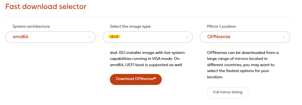
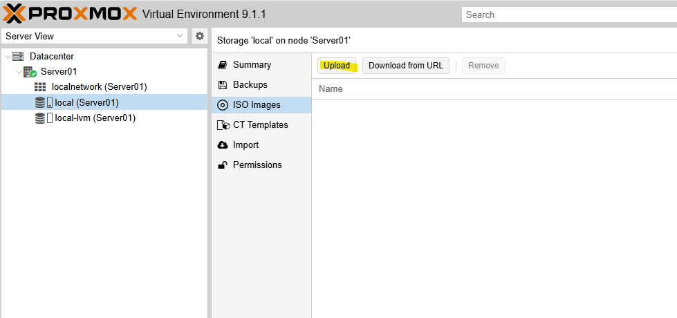
As a first step, you will need a Debian 13 ISO image, which can be downloaded here: Debian — Downloading Debian
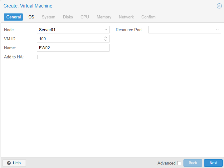
On your Hyper-V host, create a new virtual machine with the following configuration:
- Name: PBS
- Generation: Generation 1
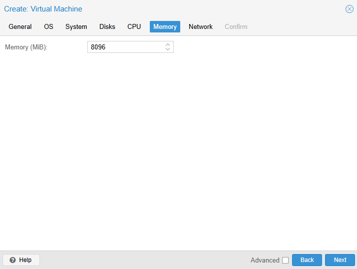
- Memory: 2048 MB RAM (dynamic memory is optional, but not required)
- Network: Your preferred network connection
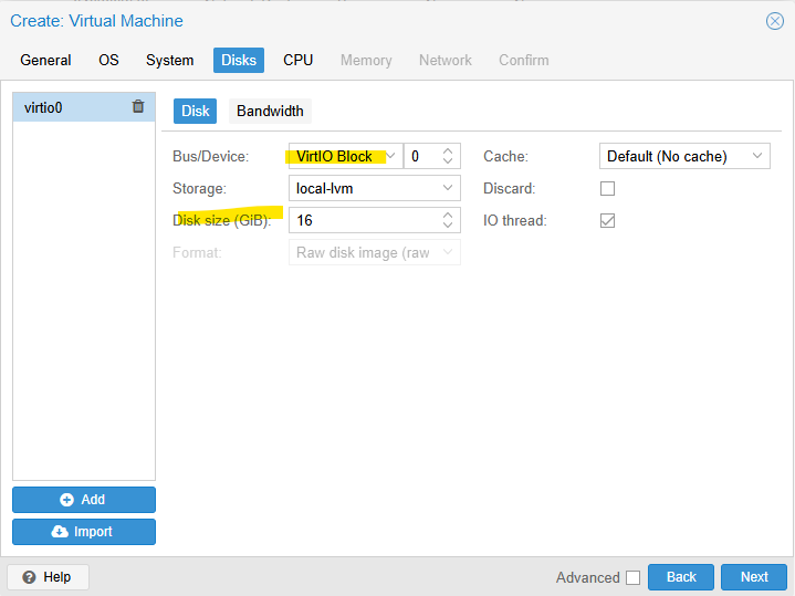
- Virtual hard disk: 32 GB
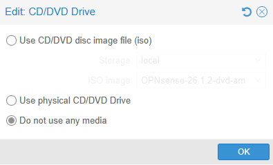
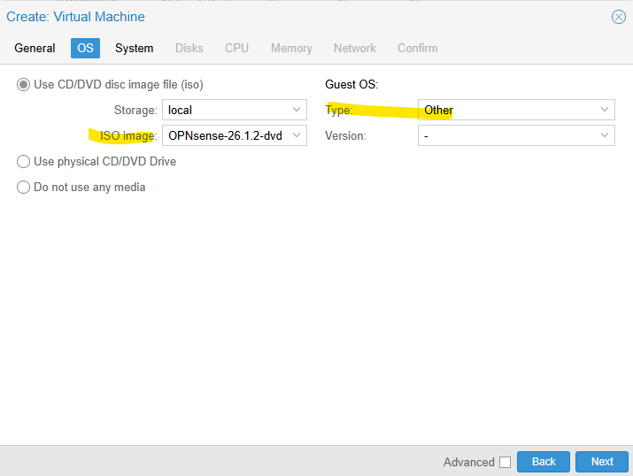
- Installation options: Install an operating system from a bootable CD/DVD-ROM
- Image file (.iso): Select the previously downloaded
debian13.iso - Once the configuration is complete, click Finish — but do not start the VM yet.
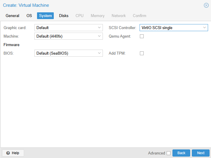
Open the VM settings and adjust the following options:
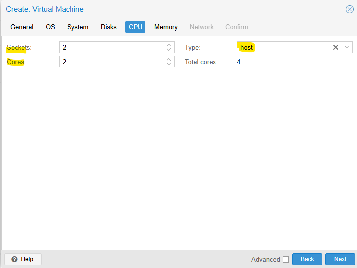
- Processors: 2 processors are sufficient
- Network Adapter: If required, configure the appropriate VLAN ID
- Integration Services: Enable Guest Services
- Checkpoints: Disable checkpoints if they are not needed
- Automatic Start Action: Set this to Automatically start if it was running when the service stopped
- Automatic Stop Action: Set this to Shut down the guest operating system
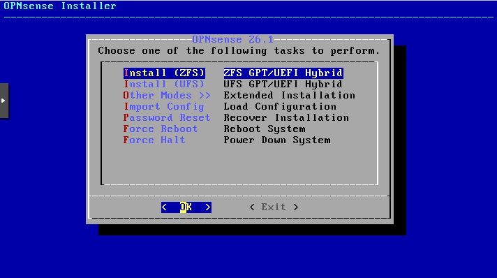
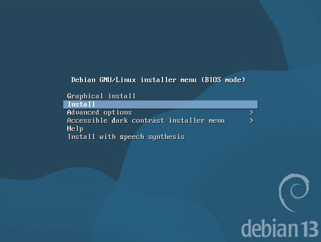
Start the virtual machine and begin the installation using the non-graphical installer.
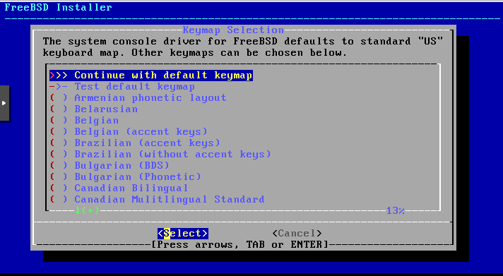
Select the desired language, country, and keyboard layout.
When prompted, set the hostname to match the VM name, for example: pbs.
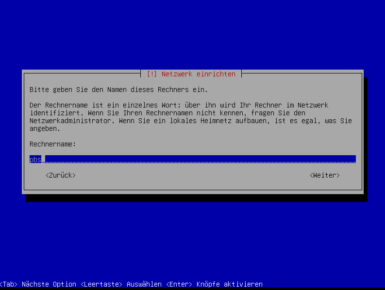
If you do not have a domain name, leave the Domain name field blank.
Set a root password.
Enter a full name for the user account. You can use something like sysop or any other name you prefer.
Then define the username, for example sysop.
Set the password for the sysop user.
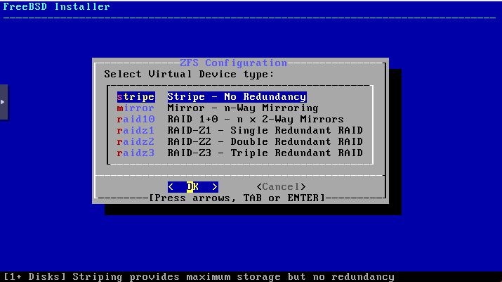
For disk partitioning, choose:
- Guided – use entire disk
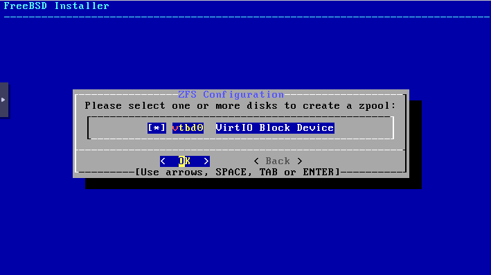
- Select the target disk
- Choose All files in one partition (recommended for new users)
Then:
- Finish partitioning and confirm the changes
- When asked whether the changes should be written to disk, select Yes
- Since the VHDX was just created, it should not contain any data yet
The operating system installation will now begin.
During the remaining setup:
- If prompted for an additional installation medium, select No
- Choose your country for the package mirror and then select the mirror server
- In most cases, the default option is fine
- If your environment requires a proxy for internet access, enter it in the next step
- Otherwise, leave the field blank
- When asked about popularity-contest, choose Yes only if you want to participate
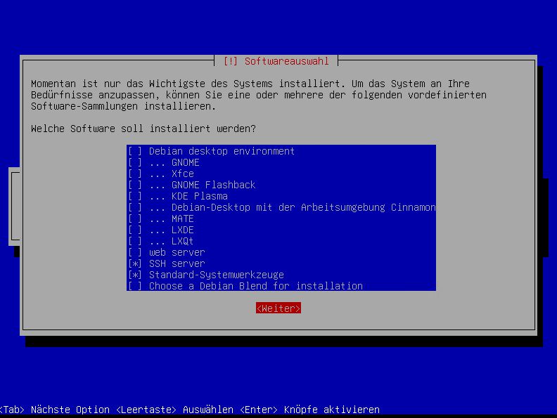
For software selection:
Only select SSH server and standard system utilities
A Debian desktop environment such as GNOME is not required
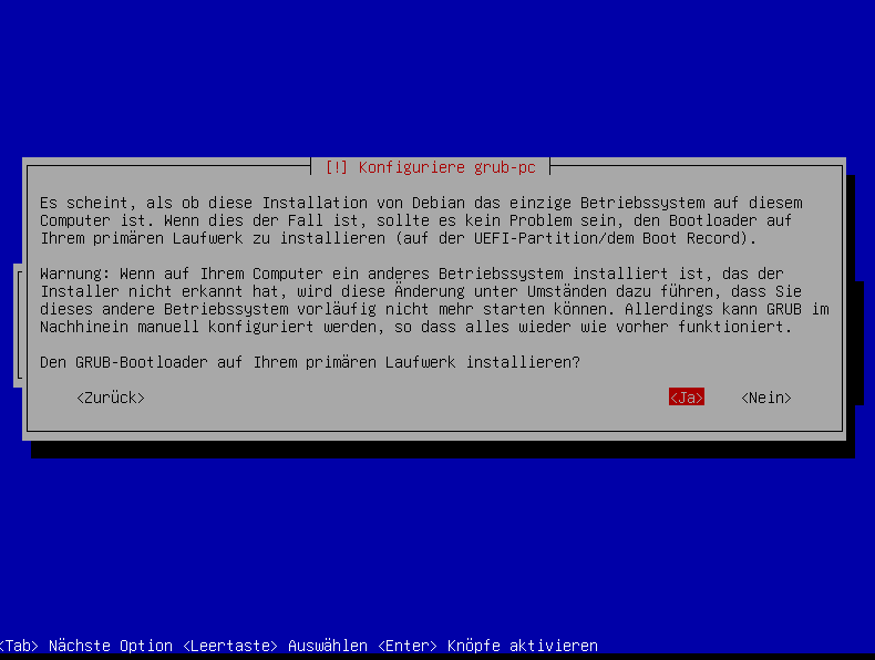
Since this system will only run a single operating system, you can safely install GRUB on the primary disk.
Select the corresponding disk for the GRUB boot loader installation.
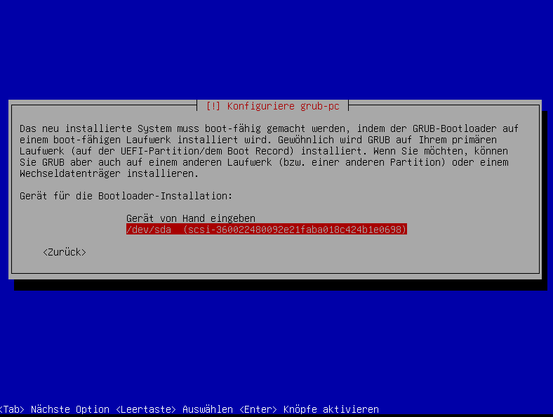
Click Continue to complete the installation. The VM will then reboot automatically.
After the reboot, log in as sysop and run ip addr to display the IP address assigned by DHCP.
ip addrYou can now connect to the VM via SSH using the IP address displayed earlier.
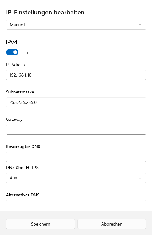
As a next step, configure a static IP address for the Proxmox Backup Server.
Please note that DHCP will no longer be used after the Proxmox Backup Server installation, so the system should be configured with a static IP address beforehand.
Then switch to administrative mode.
suand enter your root password.
nano /etc/network/interfacesAt this point, your eth0 interface is still configured to use DHCP.
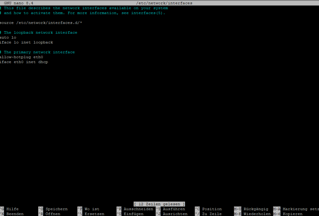
Adjust the network configuration to match your environment, for example:
# The primary network interface
allow-hotplug eth0
iface eth0 inet static
    address 10.4.4.20
    netmask 255.255.255.0
    gateway 10.4.4.1
    dns-nameservers 10.4.4.1

To save the file, press Ctrl + X, then Y, and finally Enter.Code-Sprache: CSS (css)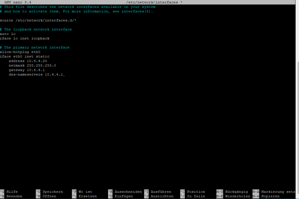
Now restart the network services.
If you cannot reconnect via SSH using the newly configured IP address, perform a reboot from the Hyper-V console and verify the network settings there.
systemctl restart networkingNAS
In the next step, create a CIFS/SMB share on your NAS and configure a user account with read and write permissions for that share.
iSCSI would generally be the preferred option. However, in my case, the NAS does not have a free storage pool available for an iSCSI LUN, so this setup uses CIFS/SMB instead.
Example share path:
\\10.4.5.200\backup\pbs
PBS
Connect to the system again via SSH and switch with su to administrative mode.
Then install the required CIFS packages.
apt update
apt install -y cifs-utils
Create the mount point for the CIFS share.
mkdir -p /mnt/pbs-nasCreate a credentials file to store the CIFS/SMB username and password.
nano /root/.smb-pbsUse the following content:
username=NASSHAREUSER
password=YOURNASSHAREPASSWORD
chmod 600 /root/.smb-pbsAdd the share to /etc/fstab to configure a persistent mount that will be restored automatically after each reboot.
nano /etc/fstab//10.4.5.200/backup/pbs /mnt/pbs-nas cifs credentials=/root/.smb-pbs,vers=3.0,uid=34,noforceuid,gid=34,noforcegid,iocharset=utf8,file_mode=0660,dir_mode=0770,_netdev,x-systemd.automount,nofail 0 0Code-Sprache: JSON / JSON mit Kommentaren (json)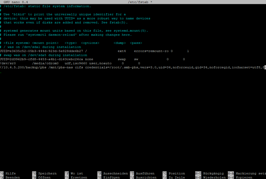
Test the configuration to ensure the share mounts correctly.
mount -a
ls -la /mnt/pbs-nas
Install Proxmox Backup Server.
mkdir -p /usr/share/keyrings

wget https://enterprise.proxmox.com/debian/proxmox-archive-keyring-trixie.gpg -O /usr/share/keyrings/proxmox-archive-keyring.gpgCode-Sprache: JavaScript (javascript)- (without subscription)
cat > /etc/apt/sources.list.d/proxmox.sources << 'EOF'
Types: deb
URIs: http://download.proxmox.com/debian/pbs
Suites: trixie
Components: pbs-no-subscription
Signed-By: /usr/share/keyrings/proxmox-archive-keyring.gpg
EOFCode-Sprache: JavaScript (javascript)- (with subscription)
cat > /etc/apt/sources.list.d/pbs-enterprise.sources << 'EOF'
Types: deb
URIs: https://enterprise.proxmox.com/debian/pbs
Suites: trixie
Components: pbs-enterprise
Signed-By: /usr/share/keyrings/proxmox-archive-keyring.gpg
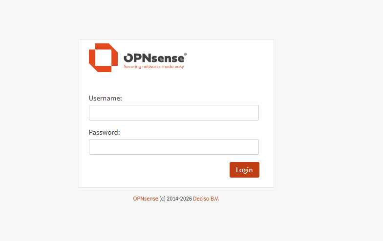
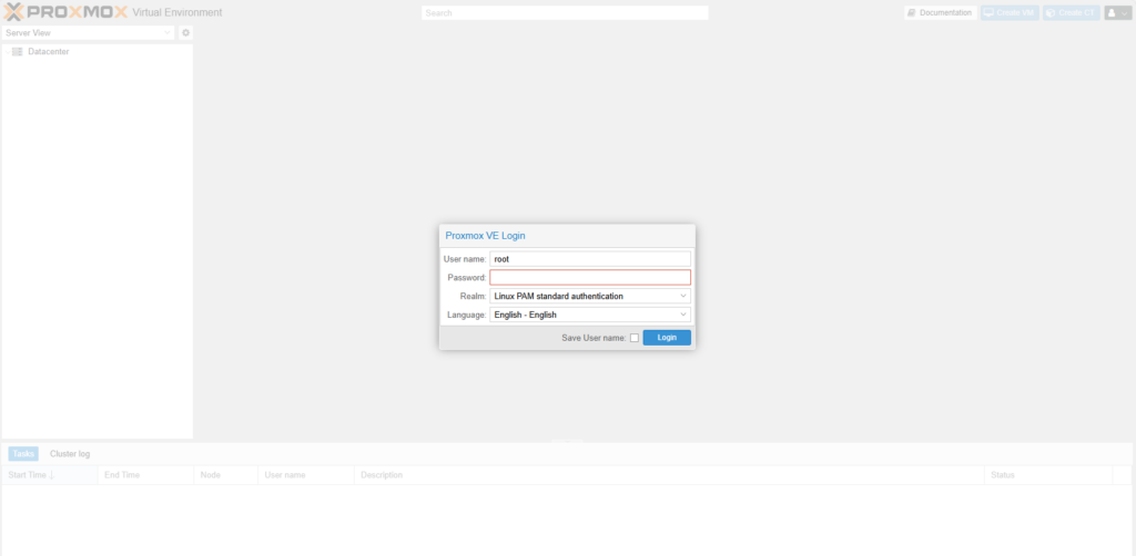
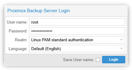
EOFCode-Sprache: JavaScript (javascript)apt updateapt install proxmox-backup-serverapt install proxmox-backup-clientNow open your browser and connect to your Proxmox Backup Server.
https://DEINE-DEBIAN-IP:8007Code-Sprache: JavaScript (javascript)Username: root
Password: Use the same password you have been working with so far
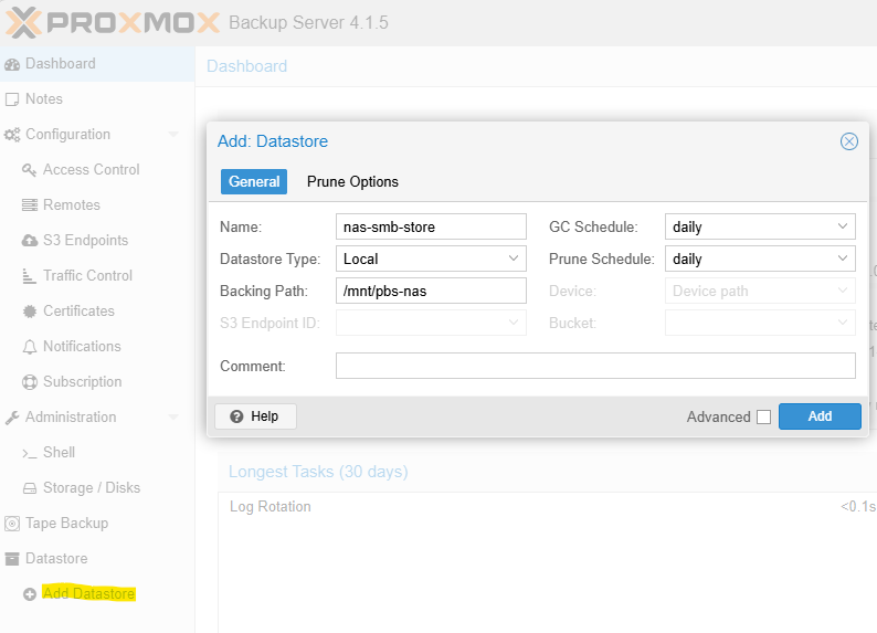
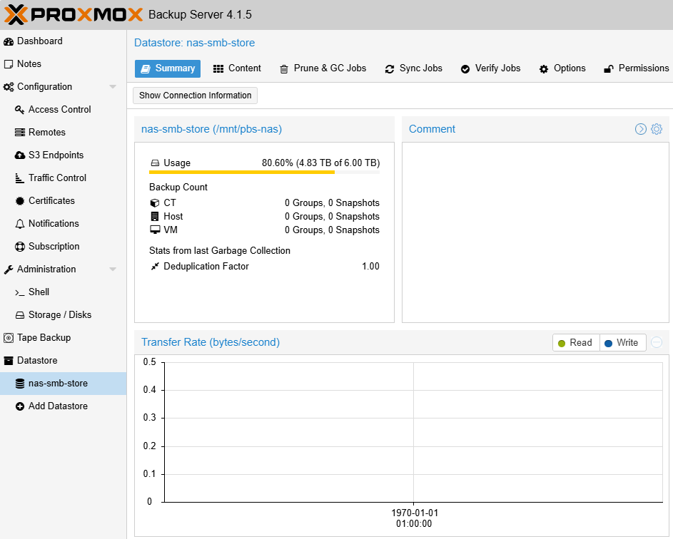
The first thing we need to create is a Datastore, which will be located on the mounted CIFS share.
Go to Datastore and click Add Datastore, then use the following settings:
Backing Path: /mnt/pbs-nas
Name: nas-smb-store
Datastore Type: Local
The datastore chunks will now be created.
It should now look like this:
When you back up a container or virtual machine, the backup data is stored using the corresponding VM or CT ID.
If you operate multiple Proxmox VE servers outside of a cluster, it is strongly recommended to work with namespaces in order to keep backups clearly separated.
In fact, creating a namespace is a good practice even if you currently have only one Proxmox VE server, as it keeps the datastore structure clean and makes future expansion easier.
When creating namespaces, use the name of your Proxmox VE host, not the name of the Proxmox Backup Server.
Example namespaces:
Server02
Server01
proxmox-backup-client namespace create Server01 --repository root@pam@localhost:nas-smb-store
proxmox-backup-client namespace create Server02 --repository root@pam@localhost:nas-smb-storeCode-Sprache: PHP (php)
Next, you can connect your Proxmox VE server to the Proxmox Backup Server.
Log in to the web interface of your Proxmox VE host and navigate to:
Datacenter → Storage → Add → Proxmox Backup Server
Then fill in the required fields with the following information:
ID: pbs-nas-smb
Server: Your PBS IP address, for example 10.4.4.20
Username: root@pam
You can also create and use a dedicated user account on the PBS if preferred
Password: The password for root@pam
Datastore: nas-smb-store
Namespace: As described in the previous step, for example Server01
Fingerprint: You can find this on the PBS dashboard, roughly in the middle of the page under Show FingerprintCode-Sprache: CSS (css)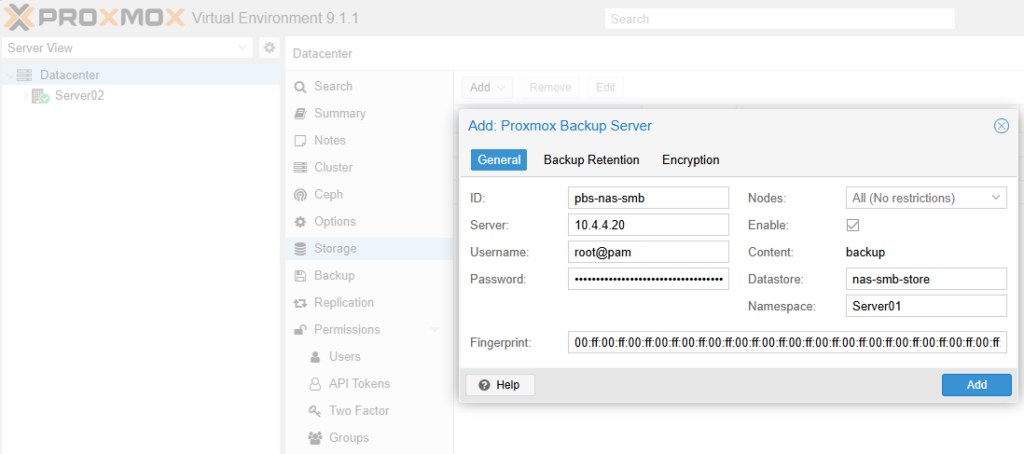
The datastore is now available. When you select a virtual machine or container, you can open the Backup tab, click Backup now, and choose the newly added storage target.
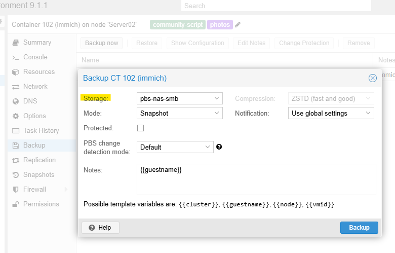
Completed backups will not appear in the per-VM Backup list. Instead, you can find them under:
Datacenter → pbs-nas-smb → Backups
You can configure scheduled backup jobs globally under:
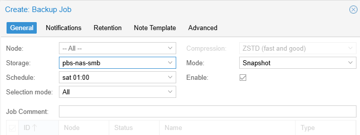
Datacenter → Backup
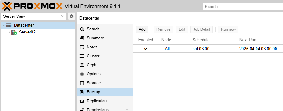
For example, you can create a job to run a full backup of all clients every Saturday at 1:00 AM
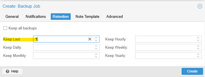
Retain a maximum of one backup version.
That’s it. Verify that temporary snapshots are removed correctly after each job and that the backups complete successfully.
Backing Up Your Proxmox Backup Server
Shut down the virtual machine in Hyper-V.
Then:
Right-click the VM and select Export
Choose the target location
Click Export
Once the export is complete, start the virtual machine againCode-Sprache: JavaScript (javascript)